Lift the Lid
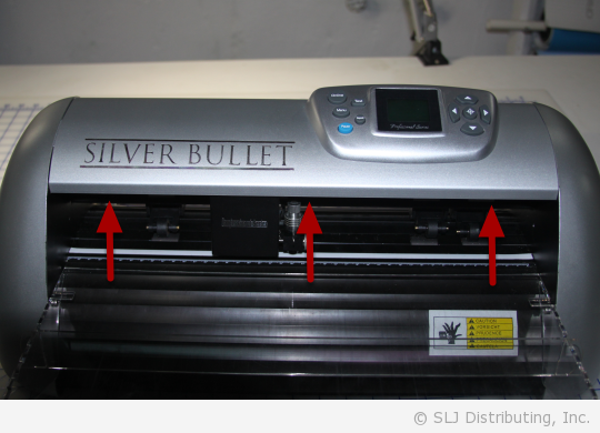
First, verify that the machine is turned off and all the cords are disconnected. Lift the Lid to reveal the circuit board on the top of the cutter assembly.
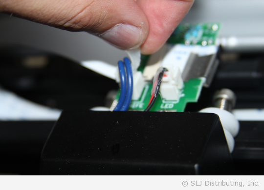
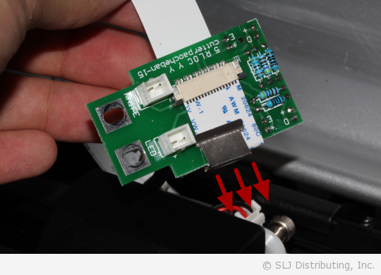
Unplug Wires
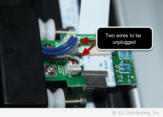
Unplug the two colored wires plugged into the circuit board. You may have to carefully remove some glue first.
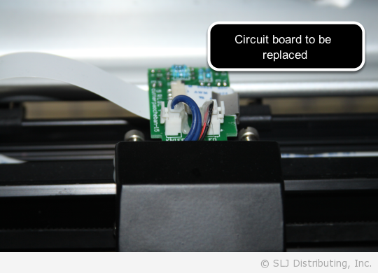
Unscrew the Circuit Board
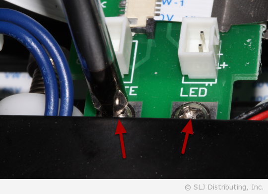
There are two screws that need to be taken out to remove the circuit board. Carefully take them out using a phillips screwdriver. Once the screws are removed, you will be able to lift the circuit board out of the machine. It will still be attached to the communication cable.
Note: Be careful not to bend the circuit board’s support bar underneath.
Pull the metal clip off of the circuit board.
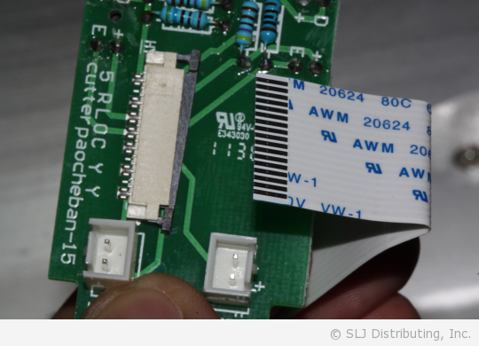
Remove the Communication Cable
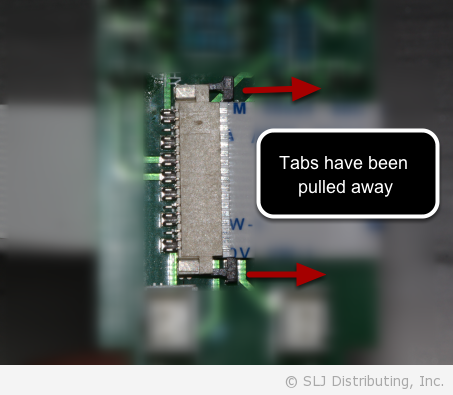
In order to remove the communication cable, you must first pull out the side tabs anchoring it to the circuit board. In the photo above, you can see that the black tabs have been pulled out.
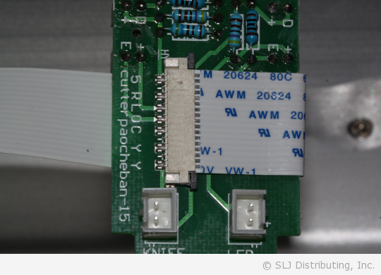
With the tabs pulled away, you can now remove the communication cable from the circuit board.
Putting the Maching Back Together
You can now switch out the circuit board. With the tabs pulled apart, replace the communication cable and push the tabs back in to secure the cable.
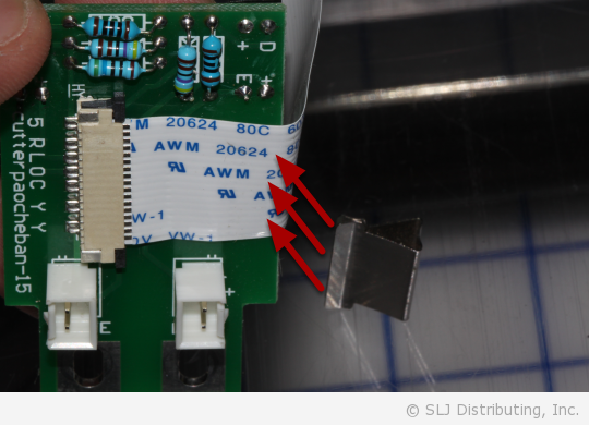
Line up the metal clip with the edge of the circuit board and use your thumb to push it onto the circuit board.
Replace the screws to anchor the circuit board back to the cutter assembly.
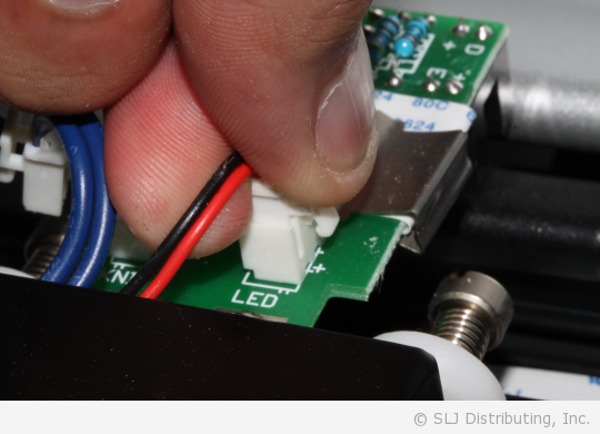
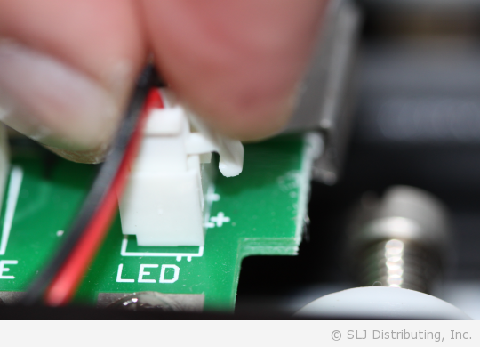
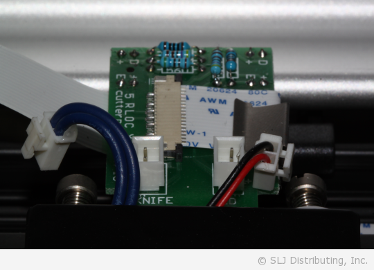
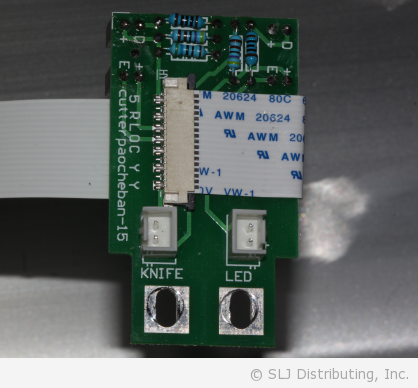
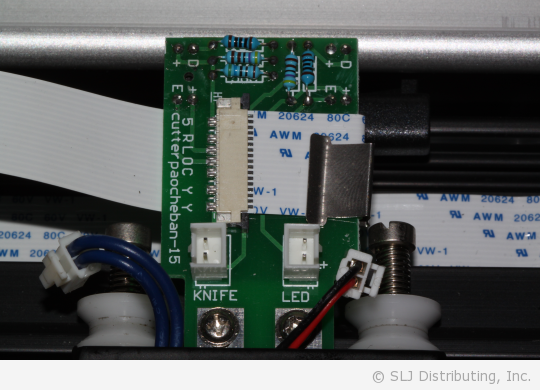
Plug the wiring back into the circuit board. The blue wires plug into the port that reads KNIFE and the red/black wires plug into the port reading LED.
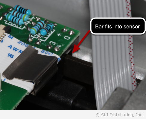
Verify Correct Fit
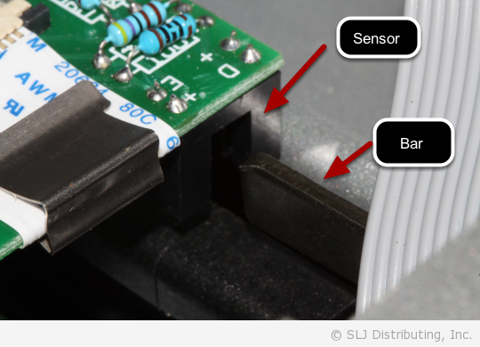
Check to make sure that the circuit board’s support bar has not been bent by sliding the carriage assembly all the way to the right of the machine. The sensor should glide over the “L-shaped” bar.